Every pilot depends on a clear set of engine instruments to keep the engine running smoothly and the airplane safe. These aircraft instruments are more than colorful dials and screens—they tell the real story of what’s happening under the cowling. They help monitor heat, air pressure, speed, fuel, and even the smallest change in how the reciprocating engine or turbine is performing.
It’s worth remembering that mechanical or maintenance-related issues still cause nearly one in five accidents in general aviation.
In aviation, understanding these readings is one of the first steps to becoming a confident pilot. The gauge you check before takeoff, the indicator you scan in cruise, and the temperature gauges that stay green in the climb—all of these tools protect both the engine and the people on board. Each instrument has a job, and when they work together, they give the pilot everything needed to fly safely at any altitude.
To kick things off, let’s start by looking at what these instruments are, how they work during flight, and what happens when one sends a warning sign.
What Are Engine Instruments and Why Do They Matter?
Every aircraft has a collection of engine instruments that help the pilot understand how the engine is running. These instruments measure oil, air pressure, fuel, and temperature gauges to show the health of the reciprocating engine or turbine. Pilots rely on these readings to measure operating parameters such as oil pressure, fuel flow, and exhaust gas temperature.
Instruments provide a clear picture of what’s happening in real time. Here are some examples of what these aircraft components do:
- Oil Pressure Gauge: Shows how well the oil pump circulates oil.
- Fuel Flow Indicator: Displays how much fuel the engine is using.
- Cylinder Head Temperature Gauge: Helps prevent overheating.
- Manifold Pressure Gauge: Measures how much power the engine is producing.
These tools are part of aircraft instrumentation, working with other aviation tools like the altimeter, airspeed indicator, and vertical speed indicator. Together, they make up a system that helps pilots keep the airplane within safe limits.
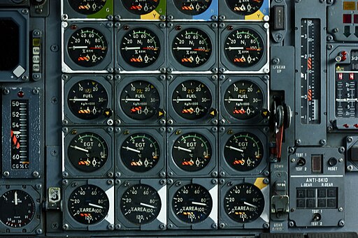
Modern planes often have a glass cockpit, where these readings appear on digital displays. Older planes might use traditional round dials, part of what pilots call the six pack. Both styles use gyroscopic instruments and the pitot-static system to read barometric pressure, pressure altitude, and airspeed accurately.
Understanding the connection between basic flight instruments—such as the attitude indicator, heading indicator, and turn coordinator—and engine gauges helps pilots maintain smooth, level flight. When a pilot monitors both flight and engine data, they can better control aircraft attitude, pitch and bank, and the overall flight path.
Engine instruments keep the engine healthy. Flight instruments like the compass, VOR, ILS, and horizontal situation indicator keep the airplane pointed in the right direction. Together, they make flying precise and safe, helping pilots track rate of climb or descent and stay aware of their position relative to sea level.
By reading and understanding all these navigation instruments, pilots can detect small changes early. That’s what makes flying smoother, safer, and far more enjoyable.
How Pilots Use These Gauges During Flight
During every phase of flight—takeoff, climb, cruise, and descent—pilots keep their eyes on the gauge readings. Each indicator tells part of the story about how the engine is performing.
Before takeoff:
Pilots check oil pressure, fuel pressure, and temperature gauges to make sure everything is in the green. They also review airspeed, altimeter, and vertical speed indicator (VSI) to confirm the pitot-static system and barometric pressure sensors are working. This step ensures the airplane is ready for safe flight control position and power response.
During climb:
Power instruments like the manifold pressure and tachometer show how much energy the engine is producing. Pilots adjust the throttle and mixture to manage fuel flow and exhaust gas temperature. They also glance at attitude indicators and heading indicators to hold the right degrees of bank, pitch and bank, and rate of climb or descent.
In cruise:
Maintaining steady altitude and airspeed becomes the focus. The artificial horizon and gyro instruments help in maintaining level flight, while the heading indicator and turn coordinator confirm a balanced standard rate turn without skid or lag.
During descent and landing:
The pilot reduces power carefully, watching temperature gauges and pressure gauges to avoid rapid cooling. The airspeed indicator, VSI, and altimeter help manage a smooth flight path back to sea level.
Pilots trained under instrument flight rules (IFR) learn to trust these gyroscopic and navigation instruments fully. Even when outside visibility is poor, readings from the compass, horizontal situation indicator, VOR, and ILS guide them safely along the intended route.
Every aircraft instrumentation system, from analog to modern glass cockpit, provides detailed feedback that lets pilots adjust power, keep balance, and detect changes quickly. In general aviation, good habits start early—learning to read every gauge means you always know what your airplane is trying to tell you.
What Happens If a Gauge Shows Trouble?
When a gauge or indicator shows something unusual, pilots respond right away. A small change on a dial can mean a big change in how the engine is feeling.
Example situations:
- Low Oil Pressure: The pilot lowers power and plans to land soon.
- High Exhaust Gas Temperature: Mixture or cooling airflow may need adjusting.
- Erratic Fuel Flow: Could signal a clogged filter or failing pump.
Every reading matters because it points to the health of the engine instruments. If the pressure gauges or temperature gauges show unusual values, pilots use checklists to diagnose the cause.
In older aircraft, lag in mechanical gyros or sticky needles can make readings slow. In a modern glass cockpit, warnings appear instantly, often with colors or sounds. Both systems rely on the same basics—air pressure, temperature, and movement—to tell pilots how the engine and airplane are behaving.
When flying by instrumentation under instrument flight rules, noticing small warnings becomes even more critical. The attitude indicator, heading indicator, and turn coordinator help the pilot keep orientation, while engine readings help keep the airplane powered correctly.
A pilot who understands aircraft instrumentation can manage unexpected readings calmly. They know that the pitot-static system, barometric pressure, and gyroscopic instruments work together to show the full picture. By tracking airspeed, altitude, VSI, and rate of turn, the pilot stays ahead of any problem.
Even in a busy cockpit filled with dials, numbers, and digital screens, awareness and habit matter most. Paying attention to every indicator—from the heading indicators to the miniature aircraft on the artificial horizon—keeps each flight safe.
When a reciprocating engine or turbine starts to act differently, the instruments provide early warnings. The pilot’s quick thinking, combined with reliable navigation instruments, makes all the difference.
13 Engine Instruments in Aircraft Every Pilot Must Know
Every airplane has a set of tools that help the pilot monitor how the engine is working. These tools are known as Gauges and Indicators, and they are some of the most important parts of the cockpit. Just like the basic flight instruments help control speed, height, and direction, engine instruments help keep the airplane’s power source healthy and safe.
Each instrument gives pilots clear numbers or readings that describe the Aircraft Condition—like oil pressure, fuel flow, or engine temperature. Together, they form a big picture of how the Aircraft Systems are performing during flight.
| No. | Instrument Name | What It Measures | Why It Matters | Typical Pilot Use |
| 1 | Tachometer (RPM Gauge) | Engine or propeller speed (revolutions per minute) | Shows how fast the engine is turning; helps control power and avoid over-speeding | Checked during takeoff, climb, and cruise to set and maintain correct power |
| 2 | Manifold Pressure Gauge | Air pressure in the engine intake manifold (inHg) | Indicates engine power level and helps balance power with RPM | Used with tachometer on constant-speed propeller engines to set power |
| 3 | Oil Pressure Gauge | Oil system pressure (psi) | Low pressure signals leaks, pump failure, or engine wear | Monitored immediately after start-up and throughout flight |
| 4 | Oil Temperature Gauge | Oil heat level (°F/°C) | Keeps engine within safe lubrication and cooling range | Watched closely in climb and cruise; helps detect overheating |
| 5 | Cylinder Head Temperature (CHT) Gauge | Cylinder head temperature (°F/°C) | Prevents overheating and detonation in air-cooled engines | Adjust mixture, cowl flaps, or climb rate to control temperature |
| 6 | Exhaust Gas Temperature (EGT) Gauge | Exhaust gas temperature (°F/°C) | Helps fine-tune fuel mixture for performance and efficiency | Used to lean or enrich mixture and check for uneven fuel distribution |
| 7 | Fuel Pressure Gauge | Pressure of fuel delivered to the engine (psi) | Ensures steady fuel delivery; detects pump or blockage issues | Checked before takeoff and during climb when demand is high |
| 8 | Fuel Flow Indicator | Rate of fuel consumption (GPH or PPH) | Helps track fuel burn and detect abnormal usage | Used with flight time and fuel quantity gauges for planning |
| 9 | Fuel Quantity Gauge | Amount of fuel remaining (gallons or liters) | Confirms available fuel; required by FAA for each tank | Cross-checked with flight time and totalizer readings |
| 10 | Carburetor/Induction Air Temperature Gauge | Temperature of air entering the carburetor/intake | Warns of potential carburetor icing conditions | Apply carb heat when near freezing or in high humidity |
| 11 | Ammeter or Load Meter | Electrical system load or charge rate (amps) | Shows health of alternator or generator system | Positive = charging; negative = battery discharging |
| 12 | Turbine Temperature Gauge (ITT/TIT) | Hot-section temperature in turbine engines | Prevents overheating and turbine blade damage | Watched closely during takeoff and climb; stay within limits |
| 13 | Torque Meter (Turboprop) | Rotational force (torque) on turbine shaft | Indicates power output to propeller | Used to set power in climb and cruise; combined with ITT for efficiency |
Here’s more a detailed look at each of the 13 most important engine instruments every pilot must understand.
1. Tachometer (RPM Gauge)
The tachometer tells the pilot how fast the engine’s crankshaft or propeller is turning. It measures this speed in revolutions per minute, or RPM.
- What it measures: The engine’s rotational speed.
- Normal range: Varies by aircraft, usually between 2,000 and 2,700 RPM for small piston airplanes.
- Why it matters: A steady RPM means smooth power delivery. If the needle drops suddenly, it could mean engine trouble or power loss.
- Pilot use: During takeoff, the pilot checks that RPM rises to the proper level. In cruise, the pilot adjusts the throttle and propeller to set the right power for speed and fuel efficiency.
In airplanes with a constant-speed propeller, the tachometer works alongside the manifold pressure gauge to fine-tune engine performance.
2. Manifold Pressure Gauge
The manifold pressure gauge measures the air pressure in the engine’s intake manifold. It helps the pilot understand how much power the engine is producing.
- What it measures: Air pressure in the intake manifold, shown in inches of mercury (inHg).
- Normal range: Usually 15–30 inHg, depending on altitude and power setting.
- Why it matters: Helps manage the engine’s workload and avoid overstressing it.
- Pilot use: Used with the tachometer to set power on engines with constant-speed propellers.
When the throttle opens, manifold pressure rises. If it falls unexpectedly, it can mean a problem like a leak or restriction in the intake system.
3. Oil Pressure Gauge
Oil pressure shows how well the engine’s lubrication system is working. Oil flows through the engine to reduce friction and cool parts.
- What it measures: The pressure of the oil circulating in the system, measured in pounds per square inch (psi).
- Normal range: Usually 30–60 psi.
- Why it matters: Low pressure can mean the oil pump is failing or oil is leaking. High pressure can mean a blockage.
- Pilot use: Check right after engine start—pressure should rise within seconds.
Keeping oil pressure in range helps protect bearings, cylinders, and other vital parts of the engine.
4. Oil Temperature Gauge
This gauge works closely with oil pressure. It measures how hot the oil gets during operation.
- What it measures: Oil temperature in degrees Fahrenheit or Celsius.
- Normal range: Around 180–220°F for many piston engines.
- Why it matters: If oil gets too hot, it loses its ability to lubricate and can lead to engine wear.
- Pilot use: During climb or cruise, pilots adjust engine power or airflow to keep temperatures safe.
Watching both oil pressure and temperature together gives the best picture of oil system health.
5. Cylinder Head Temperature (CHT) Gauge
The CHT gauge measures how hot the cylinder heads are. These readings help the pilot avoid overheating the engine.
- What it measures: The metal temperature of the cylinder head, in °F or °C.
- Normal range: Usually below 400°F during cruise.
- Why it matters: High CHT can cause engine damage like cracked cylinders or detonation.
- Pilot use: Pilots adjust mixture and cooling airflow to control CHT.
It’s especially useful during climbs or high-power settings when the engine works hardest.
6. Exhaust Gas Temperature (EGT) Gauge
The EGT gauge measures the heat in the exhaust gases leaving the engine. It’s used mainly for fine-tuning fuel mixture.
- What it measures: Exhaust gas heat in °F or °C.
- Normal range: 1250–1500°F for most piston engines.
- Why it matters: A steady EGT reading helps pilots achieve the best fuel economy without overheating the engine.
- Pilot use: Leaning the mixture until EGT peaks, then enriching slightly for cooler operation.
EGT is also a great way to detect problems like uneven fuel flow between cylinders.
7. Fuel Pressure Gauge
The fuel pressure gauge shows how much pressure the fuel pump is providing. Without enough fuel pressure, the engine can lose power.
- What it measures: Fuel line pressure in psi.
- Why it matters: Low fuel pressure may mean a pump failure or clogged filter.
- Pilot use: During takeoff and climb, the pilot keeps an eye on it to ensure steady fuel delivery.
If pressure drops, the pilot can turn on the auxiliary fuel pump to restore normal flow.
8. Fuel Flow Indicator
This gauge tells how much fuel the engine is using per hour. It helps manage fuel efficiency and flight planning.
- What it measures: Gallons per hour (GPH) or pounds per hour (PPH).
- Why it matters: Helps pilots plan fuel stops and detect if the engine is burning too much or too little fuel.
- Pilot use: Compare fuel flow readings with flight time and tank levels for accurate fuel management.
A change in fuel flow can also signal leaks or carburetor problems.
9. Fuel Quantity Gauge
The fuel quantity gauge shows how much fuel remains in each tank.
- What it measures: Volume of fuel, in gallons or liters.
- Why it matters: Prevents fuel starvation and helps balance the airplane.
- Pilot use: Always cross-check with flight time and fuel burn rate.
Although not always perfectly accurate, this gauge gives a helpful estimate of remaining fuel, especially when paired with a fuel totalizer.
10. Carburetor or Induction Air Temperature Gauge
This gauge helps detect ice risk in the carburetor or air intake. Ice can form when humid air cools quickly inside.
- What it measures: Air temperature in the induction system.
- Why it matters: Carb ice can block airflow and cause power loss.
- Pilot use: Use carb heat if the reading shows temperatures near freezing.
Staying alert to changes in induction temperature helps prevent sudden engine roughness.
11. Ammeter or Load Meter
This electrical gauge monitors how well the alternator or generator is charging the battery.
- What it measures: Electrical current in amps or the percentage of system load.
- Why it matters: Keeps track of electrical health.
- Pilot use: A positive reading means charging; a negative one means the system is discharging.
Monitoring electrical power ensures lights, radios, and flight instruments work properly throughout the flight.
12. Turbine Temperature Gauge (ITT or TIT)
In turbine aircraft, the ITT (Inter-Turbine Temperature) or TIT (Turbine Inlet Temperature) gauge shows the heat in the turbine section.
- What it measures: Hot-section temperature, often in °C.
- Why it matters: Too much heat can damage turbine blades or reduce engine life.
- Pilot use: During takeoff and climb, keep readings within limits to avoid overheating.
It’s one of the most critical readings in turbine-powered aircraft.
13. Torque Meter (for Turboprops)
This gauge measures twisting force, or torque, in the turbine shaft that turns the propeller.
- What it measures: Shaft torque in foot-pounds or PSI.
- Why it matters: Shows how much power is actually reaching the propeller.
- Pilot use: Helps set climb, cruise, and descent power accurately.
Torque readings often combine with ITT or RPM to manage engine performance efficiently.
How Engine and Flight Instruments Work Together
Pilots don’t read these instruments in isolation. They connect what they see with the airplane’s Flight Instruments—tools that help control direction, height, and speed. The Six Basic Instruments often called the 6 pack, include the Airspeed Indicator, Attitude Indicator, Altimeter, Turn Coordinator, Heading Indicators, and Vertical Speed Indicator.
These instruments depend on the Pitot-Static System, which uses air moving through the pitot tube and static ports to measure Feet per Minute changes in altitude, airspeed, and pressure. They help pilots maintain Aircraft Attitude, direction, and smooth control on all three axes—pitch, roll, and yaw.
Together, engine and Flight Instruments form a complete picture of the airplane’s performance. For example:
- The Vertical Speed Indicator shows the rate of climb or descent in Feet per Minute.
- The Heading Indicators help pilots stay on a directional course.
- The Attitude Indicator shows Aircraft Attitude, which helps keep wings level.
- The Turn Coordinator confirms proper coordination during turns without slipping or skidding.
All of these help the pilot understand how the airplane moves through the air. The Pitot-Static System gives precise readings of pressure and altitude, while the gyroscopic instruments like the Heading Indicators and Attitude Indicator show balance and orientation. They help maintain control even when flying through clouds or low visibility conditions.
How These Systems Fit into Aircraft Design
Inside every plane, the Aircraft Components are designed to work in sync. The Aircraft Systems include the engine, fuel, electrical, and hydraulic parts. The tail section, or Tail of the Plane, helps balance the airplane and control movement along its axes.
Other important systems include Auxiliary Power Units, which provide power when the main engines are off, and backup systems that keep critical instruments working during emergencies.
The pilot’s job is to keep all of this working together. By scanning both the Gauges and Indicators, they can detect changes early—before a problem becomes serious. Monitoring the Aircraft Condition means checking the engine, flight instruments, and all systems regularly. It also means understanding how each Aircraft Component supports safe operation.
Building Confidence Through Knowledge
Learning about these instruments helps new pilots feel more confident. It builds habits that make flying safer and smoother. Pilots often practice scanning the 6 pack and engine gauges together until it becomes second nature.
Even experienced pilots review readings carefully during each phase of flight. They know that small changes—like a rise in oil temperature or a drop in Fuel Flow—can tell them a lot about what’s happening inside the engine.
Instructors teach students to connect what they see on the Gauges and Indicators to what they feel in the controls. If the Aircraft Attitude or climb rate feels off, a quick look at the Vertical Speed Indicator or Heading Indicators can confirm it. These habits make every pilot more skilled and more aware.
Conclusion
Every pilot benefits from understanding these 13 engine instruments in aircraft. They are the heart of safe and smart flying, connecting technology and human awareness. Each reading, each dial, and each digital number gives pilots the knowledge to make confident decisions in the air.
When used with the Flight Instruments and supported by strong Aircraft Systems, they give the pilot everything needed for safe and efficient flight.
By understanding what every gauge means and how it connects to the airplane’s movement, pilots can stay calm, make quick decisions, and keep the Aircraft Condition in top shape.
Flying becomes safer, smoother, and more rewarding when pilots read the instruments with confidence, care, and a touch of curiosity!
Learning to read these instruments takes practice, patience, and curiosity—but it’s one of the most rewarding parts of becoming a pilot. Keep studying, keep scanning, and keep flying smart.
Want to learn more about what makes flying safer and more enjoyable? Visit Flying411 for clear, pilot-friendly tips and guides today!
Frequently Asked Questions
What is the purpose of engine instruments?
They show the pilot how the engine is performing by measuring temperature, pressure, and fuel systems.
How often do pilots check their engine gauges?
Pilots check them before takeoff, during climb, in cruise, and again before landing.
What if one of the gauges stops working?
Pilots use backup indicators and follow emergency checklists to land safely.
Do all aircraft have the same engine instruments?
Most have similar types, but layouts and numbers vary by model and engine type.
How does a glass cockpit help?
It combines multiple instruments into one display, making it easier to monitor readings quickly.


